 VALVE SPRINGS
By Bob Markiewicz
We all have that friend who has a thankless job, you always hear about how someone other then them always gets credit for all their hard work. The valve springs in your racing engine are in the same position, but they normally don’t say anything until it is too late. The cam always seems to get all the attention, people are always asking what cam are your running, but never have I heard what springs are you using? Yes, the cam is the most sophisticated part of your valve train, but without the proper valve springs the cams full potential would never be met. If you put too much valve spring in your engine you are just costing yourself horsepower due to increased friction. If you have too little, the engine will run into valve float costing you power and rpm. Having the right balance of spring tension is critical to being competitive on race day.
I understand that you are probably not going to be designing your own valve springs for your race engine. That doesn’t mean that having a better understanding or your valve spring won’t be a benefit. This knowledge can help you more effectively communicate with your engine builder, or even find problems more efficiently at the track. Even though most don’t think of them this way, valve springs are wear components that do require replacement throughout the racing season. Springs take a lot of abuse and replacing them is cheap assurance that your engine is reaching its full potential. At 7000 rpm your springs have to go from being still, to full valve lift, and back to still 58 times in one second. If your average engine speed during a race is 6000rpm and your race takes 10 minutes that is 30,000 cycles!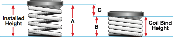
The purpose of the valve spring is to keep the related valve train components following the cam shaft profile by pushing everything against the cam. At low speed this is relatively easy, but as speed goes up the inertia of the valve train components make this a difficult task. Inertia increased with the square of speed, so this means doubling the rpm requires 4 times the force to do the same job. This is why high rpm valve trains require a lot of attention. Not only because the spring tension gets to be so high, but also because the other components must be stiff enough not to deflect under these high pressures.
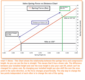
Valve springs have 2 major force measurement points when installed in the engine. The installed height and over the nose, or valve closed and valve open force. The installed height is the height of the spring when the valve is not being lifted and is sometimes referred to as seat pressure; meaning the valve is still on the seat. The over the nose or max lift point refers to the spring’s height when the cam has lifted the valve to max lift. The cam manufacture will either give a specific spring and height to install it at or just give the pressures needed at these two points.
Another big consideration of installing a spring is coil bind. Coil bind refers to the spring’s coil being stacked up and touching each other so it can no longer be compressed. This can have catastrophic effects on your valve train and lead to many ruined parts. Always make sure that you have enough room to avoid coil bind and that at max lift you still have about .060” or more of spring travel left.
Spring force is measured in pounds, which are sometimes confused with psi (pounds per square inch) which is a pressure. The measurement is the spring’s stiffness or force, so if the spring has 30 lb. of force at the installed height it would take 30 lb of weight pushing down on the spring to make it compress to this height
Most springs have a linear force vs compression characteristic. This means, if the springs height is reduced in half then the pressure is doubled. This makes calculating the forces of the spring for a particular application relatively easy. If you know the difference in length and the change in pressure you can come up with the spring’s rate or pounds per inch. The manufacture will normally call out the spring force at two lengths. So, if a spring has 15 lb of force at an installed height of .9” and 65 lb at 1.150” the rate would be 200 lb/inch. Because:
Change in Force/Change in length= lb/inch
So, 65 lb-15 lb = 50 lb = 200 lb/inch
1.150”-.9” .25”
Now that the spring rate is known from the manufactures rating or what you have measured yourself you can easily apply it to your engine and adjust it as needed. Let’s say your cam calls for 20 lb of seat force instead of the 15 lb that you currently measured at your installed height. At 200 lb/inch 5 lb is equal to .025” of compression (1 in/200 lb=.005 in/ lb). By installing .025” of shim under your spring you can raise the seat pressure by 5 lb to achieve the 20 lb of force. If the over the nose, or max lift pressure is off then the spring rate has to be changed to achieve the desired force and this can only be done by changing the spring itself.
I realize that this sounds pretty complex, but for the most part your cam manufacturer has done all the hard work and can suggest what you need. This means that you don’t have to spend time on the dyno or track finding this right combination. However, it is still recommended that you check the installed, and over the nose pressure to make sure the spring is correct, if it isn’t then this should help you get it back to where it belongs. In a lot of what we do spring shimming is not allowed. Replacing the spring is the only way to fix an issue if you do find your measurements out of spec.
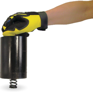
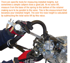
Measuring the spring force is just a matter of force versus length. By measuring your installed height in the engine you get the installed height. If it measures .830” then by subtracting your max cam lift you can get the over the nose height. With a cam lift of .255” this works out to .575” because ( .830”-.255”=.575”). Now that you know the length of the spring when the valve is at no lift and max lift all you have to do is measure the spring force at these two distances and compare them to the cam manufacturer’s recommendation. See the photos on page 27 for the operation of this essential tool.
Engine builders will normally use more complex spring measurement fixtures. This improves on the accuracy, efficiency, and repeatability which are required for serious engine development. For the average racer the small vise style tools are more than adequate.
I know you are thinking, this is all great, but how does it affect my racing? To prove the importance of this I moved over to thedyno to put some data behind all this theory. The engine tested was a middle of the road WKA Animal set up for sprint racing. The testing included a baseline with the standard as raced springs, followed by lower tension and then higher tension springs. The objective was to prove that by going too little or too far with your spring force results in much the same effect, a dramatic loss of horsepower.
The engine had 3 baseline tests ran on it with the normal racing springs installed. All 3 tests repeated within .1hp of each other so this proved the engine was good and stable. The engine was tested in two ways, steady state and accelerated or transient test. Steady state means that the engine was loaded by the dyno to stay at an rpm point for 30sec each. The engine would sit at 3500rpm for 30sec while the dyno measured its power and then would go to 4000rpm for 30sec and record again, and so on up to 7500rpm. With an accelerated test, the engine is swept at a rate of 150rpm per second from 3500rpm to 8000rpm and power measurements are taken very fast while it is being accelerated. The engine never stops at a point; much like when a kart accelerates.
The advantage of a steady state test is it sits at a rpm point long enough for the dyno operator to see what is going on; it also allows the engine to build more heat. The advantage of the accelerated test is it records at every rpm point while it is accelerating, so it doesn’t miss any dips that could fall between the steady state rpm points.
 Testing valve springs can be very unpredictable and unstable so using both test methods helps find any issues that could show up. After the baseline power was established the intake valve spring was replaced with a much weaker spring. The original force was 12 lb installed and 62 lb at max lift for both the intake and the exhaust. The replacement spring measured only 5.5 lb installed and 51 lb at max lift. To start with, only the intake valve spring was changed out, this allows the effects of the reduced force to be isolated to one valve at a time. Chart 2 shows what affect it had on the engines power output. Notice the big dip in the curve at 7000rpm, this occurs because the valve is not following the cam correctly due to the reduced pressure. Remember how I said the power is unpredictable by 7500rpm? The power comes back during the steady state test. Because the karts we race only have one gear ratio, when the power drops like this chances are the kart will stop accelerating and never make it to the point where the power picks up again. On the track this would be a very flat engine, it would feel weak above 6500rpm.
Valve float like this normally has a rev limiter type of an effect. It even sounds similar to a rev limiter at times. The engine’s exhaust note will change and sound hollow, the engine will stop revving, and the carb will show excessive spit back. By the time valve float has gotten to this degree, power has probably been falling off many RPM’s before this. If your engine isn’t acting right listen for these symptoms to help diagnose a bad spring.
During the accelerated test with the reduced force intake valve, the power was also down in the mid range. (Chart 3) Most of us know the term slapper cam when it comes to the Raptor engine. Because in most classes the cam profile and lift are limited by class structure, total power output is also limited. However, if the optimum profile and spring pressure are used, the engine can actually make the cam look much bigger by throwing the valve off the lobe in the region of max lift. This maximizes the power above what is normally limited by the rules but the cams still fall into spec when measured in the tech barn. This is different than loosing control of the valve train like seen here. Most of the “valve float” problems don’t originate over the nose of the cam but actually come from the valve not closing correctly. The valve bounces off of the seat at closing and interrupts the next cycle of the engine. Remember that the valves job is to seal the chamber when shut, obviously a bouncing valve can’t effectively do this.
 For the next test the weak valve spring was switched over to the exhaust side. Spring pressure now measured 12/62 lb on the intake and 5/51 lb on the exhaust. The results for this were so low that I reran the standard test again and came back to it to prove that the test was accurate. Anything after 3500rpm showed up as a dramatic power reduction. Though I am not a valve train dynamics expert, I do have a theory as to the differences between the two tests. When the intake valve is closing, the piston is on its way up during the compression stroke, this would create pressure and help the valve stay closed and minimize power reducing bounce. On the contrary, when the exhaust valve is closing, the piston is descending in the bore to induce the intake charge. So, instead of a pressure helping close it, now there is a vacuum helping induce the bounce.
*This sparks the thought that power might be had by staggering the intake and exhaust spring force to achieve the optimum balance between the two. This may warrant more dyno time to investigate the possibility of a “legal” power increase.
This makes it pretty clear that insufficient spring force isn’t going to put you into the winner circle. On the other side, what happens when an excessive amount of spring force is used to guarantee that you don’t see this power robbing valve float. To answer this question the engine had springs designed for a modified engine installed. In this situation higher spring forces are necessary because of the higher valve accelerations and increased engine speed. The intake force now measured 52.5 lb installed/ 94.5 lb over the nose, and the exhaust measured 51 installed/93.5 over the nose. In theory, running too much force will cause undo wear on the valve train, and most importantly an increase in friction. Unneeded friction is a waste of valuable horsepower. As you can see by Chart #6 the power loss is no insignificant amount, it is enough to dramatically affect your on track performance. The frictional power loss increases with engine speed until it reaches a point where the higher spring force starts to become more necessary and the loss start to taper off. The peak power loss was .4hp, or looking at it another way you could gain .4hp by getting the springs right.
This is a lot to take in, but remember this was an extreme example to prove out the theory. Simply put, running too much or too little spring force can both affect your engines performance negatively. Get it right and your engine will spin freely and still make maximum power. Remember that the cam manufacturer and engine designer have all worked this out so you don’t have too, unless you are doing something custom, listen to their advice and you are almost guaranteed success. Use this knowledge to help hear what your valve springs might be telling you or to set up your new springs and it may save you a race some day.