PVL IGNITION COIL

By Bob Markiewicz
The newly released ignition system from Briggs and Stratton is an innovative step for 4 cycle racing engines. It replaces the transistor type coil that was designed over 25 years ago with new digital technology. The new PVL digital system provides the racer with a product that is lighter, more robust, and more accurate than the systems of the past. The digital technology available today made it possible to develop this affordable system for our racing application. Unlike most digital systems, it only requires the integrated magnet in the flywheel to power the system.
The new PVL system can be utilized on all 3 of Briggs and Stratton’s kart racing engines; the Animal, World Formula, and Raptor can all be easily retrofitted. Starting in 07 both the Animal and World Formula will be available out of the box with this new technology. The system should prove to be comparable to the old system yet still posses some qualities that will make it a justified change over for the competitive racer.
PVL, located in Germany, specializes in the production of digital ignition systems for many performance applications. They started producing ignitions in 1970 and have since formed a reputation for producing high quality products around the world. PVL manufactures ignition components for such companies as BMW, Buell Motorcycles, Mercury Marine, Polaris, Vortex and numerous others. Their top notch ISO 9001 certified manufacturing facility proves to be the perfect match for producing the new Briggs and Stratton racing coil. They have the experience, technology, and quality that is required to make a reliable system for today’s 4 cycle kart engines.
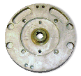
The new PVL coil is physically bigger in size. This is because it must have enough spread of the coil legs to pick up energy from the flywheel magnet and power up the system before the plug is fired. This allows it to “think” and have the ability to adjust the spark timing independent of the magnet position to the coil. The coil’s bigger physical size is of no negative affect to the engine. The coil is designed to mount in the same location as the original coil on all 3 of the race engines. Christy Matuszewski, the Motorsports engineer at Briggs and Stratton assures us that extensive thermal surveys were done to verify that the coil has no adverse affects on engine temperatures. The concern was the bigger coil could affect the air paths from the cooling fan to the cylinder. Testing proved that the new coil had no effect, neither positive nor negative, relative to the standard coil. The flywheel is constructed of a die cast aluminum main body with an integral steel center hub. The steel center hub makes for a more rigid design capable of maintaining a consistent taper when removed and replaced multiple times. This rigidity helps combat loss of timing due to a slipped flywheel. The integrated steel hub also has provisions to be used with a professional style flywheel puller. This center pulling flywheel puller is a more efficient way to remove the flywheel for the engine builders. Check out the tool of the month section on page 38 for highlights of its operation.
The flywheel incorporates a rare earth magnet that is cast into the outer edge and pinned into position. This magnet produces the energy to power the whole system, including powering up the control module and firing the spark plug.
The coil’s operation is more complex than the original transistor coil because of its digital characteristics. The theory of general operation is much the same. The flywheel magnet passes by the lamination stacks, as the opposing poles pass the legs of the coil energy is transferred up the lamination stacks to produce the energy needed to power the electronics and produce the spark. The original coil had a north-south-north pole orientation as the flywheel passed by the coil legs. The new PVL system has the pole orientated in a south-north configuration which is required for the proper operation of the coil. Unfortunately, this means that the new coil will not operate with flywheels from past designs. But, rest assured, companies like ARC Racing already have drawings in the works for aftermarket flywheels that will utilize this new pole orientation for modified applications where a different flywheel may be preferred.
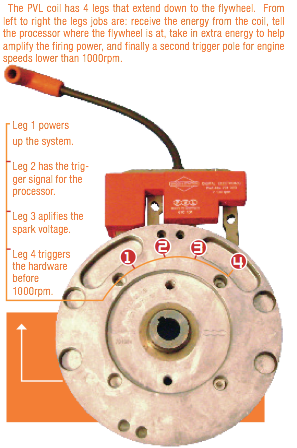
The following is a breakdown of the coil’s operation as the flywheel magnet passes by the coil legs. The magnet passes by the coil from left to right with the leftmost leg seeing the magnet first. The left leg uses the energy it gets from the magnet to charge the capacitor (electronic storage device) for future use for firing the plug and to power up the processor. The processor’s job is to tell the plug when to fire in reference to the crank position and relative to what has been programmed into it. The system is two-dimensional; this means that it adjusts the timing relative to the engine speed only. In other words the timing can be varied up or down depending on the current speed of the engine.
 The processor’s main job is to monitor the engine’s speed and tell the capacitor when to discharge, or send power to the coils to produce spark. By calculating the speed of the engine and the correct amount of time needed to produce the desired spark, the system can precisely position the timing of the ignition. The first leg of the coil produces the power to get all of this started.
The second leg is the trigger reference for the processor. This trigger location is used to calculate the spark advance and pick up the engine speed as the flywheel magnet passes by it. By calculating how much time it takes for the engine to make one revolution it can calculate the average engine speed and make adjustments to the timing as required.
The third leg’s function is to help aid in spark energy output. The CDI (capacitive discharge ignition) uses the energy stored in a capacitor to send current to the primary coil which is ultimately stepped up in the secondary coil to produce the high voltage needed for spark. This third leg gives the system the positive feature of having a secondary current source which helps amplify the capacitor’s voltage at the time of spark and ultimately increase the spark’s duration. When the timing is set within a certain range, as it is in our particular case, the spark duration is amplified because of this extra energy. In fact, so much that its spark duration is actually longer than its transistor counterpart in certain areas of the speed curves. This increased energy associated with the third leg’s position is only affected by what is programmed into the processor and is independent of the flywheel’s position at the crank. PVL has optimized this for us so the system not only offers the greater voltage potential associated with the CDI type ignition, but also has the longer spark duration normally only seen by transistor type coils.
The fourth leg (furthest to the right) is also a trigger leg. This trigger leg is used in place of the second leg that works with the processor at engine speeds lower than 1000rpm. This is considered the hardware trigger and is there to provide spark before the microprocessor has enough energy to operate. Only during start up is this hardware trigger utilized. At engine speeds greater than 1000rpm the processor takes over and uses the second leg to get its trigger information. The hardware timing is set at 10deg with the standard keyway position to allow for easy starting. Then it has 19 additional degrees of advance even before the engine gets to its idle speed, thus equaling 29degs of total advance. This timing layout helps maximize the spark energy by positioning the third leg in the right location for maximum voltage output as discussed previously.
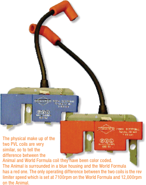
The coil’s processor also has a rev limiter that can be programmed into it. This was one of the primary assets of the new system for the World Formula racing engine. In the past the World Formula engine had an external rev limiter box that just had a wire going to the standard coil. This system was easy to disconnect leading to a possible tech issue. The World Formula’s rev limiter is now built into the processor so disconnecting it is impossible. The rev limiter is set to the same speed as the original, 7100rpm, and has a max variation of +/-1% of limiter speed. But, testing to date has shown it to be within +/-10rpm. The World Formula and Animal coils are similar in physical design. To distinguish between the two the World Formula coil is surrounded by a red casing and the Animal by a blue one.
 Because the coil is digital and programmable, there is some concern that hackers might be able to reprogram it. This would allow them to fine tune it for their application or possibly increase the rev limiter speed. I have been reassured that this is not possible due to the make up of the processor. There are many types of processors and some are reprogrammable, and others, like this one, can only be programmed one time. There is no way to reprogram it more than once and if a change of the program is needed a new one must be utilized. PVL programs the processor at the factory, thus it has been already programmed once and can’t be programmed again. Even if it could, PVL has developed its own programming language which would be next to impossible to copy to actually change the coil’s outputs. Even if it could be reprogrammed the hackers would have to get through the potting material. The entire system is potted inside the plastic housing including many of the fine wires and components that are surrounded by this epoxy-like coating. Accessing the electronics without disrupting all the circuits would be a feat within itself.
Another concern that some have is the fact that many digital systems are very sensitive to overload and can burn down easily. One way it can see an over load is if the spark plug wire is removed. Rest assured that this system is protected against such conditions. Contrary to some myths, the system will not fail if the spark plug wire is removed while the engine is running. Nor will it fail if the engine is turned over with the spark plug wire not hooked up. The system has proven to be very robust, and Christy Matuszewski of Briggs claims that through 1000’s of hours of development testing never have they failed one coil.
How does the PVL output compare to the original ignition? The properties of the CDI give it greater power potential because the primary coil has more energy to work with. The capacitor can store as much as 200volts that is instantly discharged when the processor tells it to fire. The original coil only has the energy provided by the passing magnet which is much lower. Because the two coils basically work like a step-up transformer finding the secondary output voltage is a matter of multiplying the primary coil voltage by the winding ratio of the primary and secondary coil. This means the multiplication of the primary voltage is much higher with the new CDI because of the high voltage stored in the capacitor. The system ultimately gives a higher voltage potential at the plug because this higher primary voltage is then multiplied by the coil ratio.
But remember, the plug will only use the voltage that is required to jump the gap. This voltage requirement will increase as the pressure inside the cylinder increases or the plug gap is increased. So the increased voltage potential of the PVL comes into play if the plug gap is increased and/or more compression is added. Opening up the plug gap could show possible performance gains by initiating a stronger initial burn; a possible but not yet proven advantage of the CDI system for our application. Stronger potential voltage can also help fire through a wet and fouled plug.
 The weight of the flywheel for the new system is also lighter and possesses less inertia. This means that it requires less power to accelerate it, allowing for more power to be utilized at the wheels. The difference may be negotiable, but the fact is that it is lighter, especially when compared to the original cast iron version of the World Formula’s flywheel. This lighter weight will only prove to help, not hurt, the engine’s performance.
The change over to the new system is going to require some growing pains. Hopefully, with the help of NKN and all the work that Briggs and Stratton has put into this new system, these pains will prove to be far and few between. Briggs has positioned the flywheel’s keyway where it will work well for most of our racing needs; if an adjustment is required the write up in this issue should help in fine tuning your engine. Change is never easy, but when it is a change for the better it should make good sense to the racer that change isn’t always bad. The unfortunate added expense has many added benefits for our racing engines. After the initial transition, I think most will agree that this new technology in 4-cycle racing is in the best interest for all of us. Racing requires stability, but it should also possess technologies that help progress the generations of Motorsports; otherwise, our car counterparts would still be racing with Model T’s.


 Good to know!


